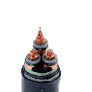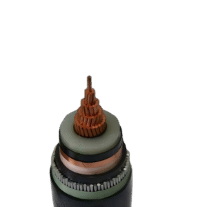
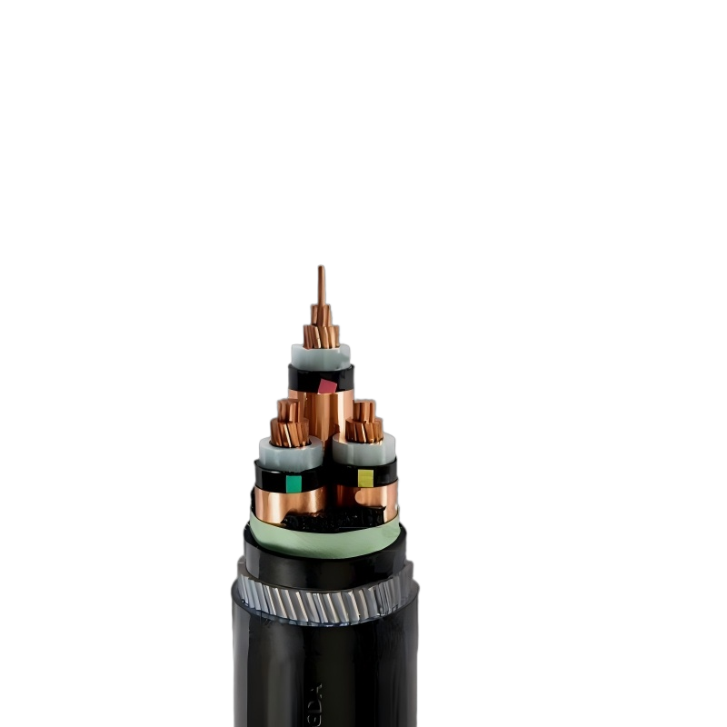
Three Core 8.7/15KV Medium Voltage Steel Wire Armoured Cable Application
The three core cables are designed for distribution of electrical power with nominal voltage Uo/U ranging from 3.6/6.6KV to 19/33KV and frequency 50Hz. They are suitable for installation mostly in power supply stations, indoors and in cable ducts, outdoors, underground and in water as well as for installation on cable trays for industries, switchboards and power stations.Three Core 8.7/15KV Medium Voltage Steel Wire Armoured Cable Construction
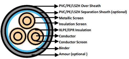
Conductor: Plain annealed copper or aluminium complying with IEC 60228/BS 6360. Copper conductors shall be stranded (class 2) and aluminium conductors shall be either solid or stranded (class 2).
Conductor Screen: Extruded layer of semi-conducting cross-linkable compound is applied over the conductor and shall cover the surface completely. The minimum thickness is 0.3mm and the maximum resistivity shall not exceed 500 Ohm-m at 90°C.
Insulation: Insulation is of cross-linked polyethylene compound XLPE (GP8) conforming to BS 7655-1.3 or EPR (GP7), conforming to BS 7655-1.2.
Table 1. Insulation Thickness
Nom. Cross Section Area | Insulation Thickness at Nom. Voltage | ||||
3.8/6.6KV(Um=7.2KV) | 6.35/11KV(Um=12KV) | 8.7/15KV(Um=17.5KV) | 12.7/22KV(Um=24KV) | 19/33KV(Um=36KV) | |
mm² | mm | mm | mm | mm | mm |
70 – 185 | 2.5 | 3.4 | 4.5 | 5.5 | 8.0 |
240 | 2.6 | 3.4 | 4.5 | 5.5 | 8.0 |
300 | 2.8 | 3.4 | 4.5 | 5.5 | 8.0 |
400 | 3.0 | 3.4 | 4.5 | 5.5 | 8.0 |
Above 500 | 3.2 | 3.4 | 4.5 | 5.5 | 8.0 |
Inner Covering & Fillers: For cables with a collective metallic layer or cables with a metallic layer over each individual cores with additional collective metallic layers, semi-conducting inner covering and fillers shall be applied over the laid up cores. The inner covering is made of non hygroscopic material, except if the cable is to be made longitudinally watertight. The inner covering shall be extruded or lapped.
The approximate thickness of extruded inner coverings is given in Table 2:
Table 2. Approximate Thickness of Extruded Inner Coverings
Ficititous Diameter over Laid Up Cores | Approx. Thickress of Extruded Inner Covering | |
mm | mm | |
> | < |
|
35 | 45 | 1.0 |
25 | 35 | 1.2 |
35 | 45 | 1.4 |
45 | 60 | 1.6 |
60 | 80 | 1.8 |
80 | – | 2.0 |
*The approximate thickness of lapped inner coverings shall be 0.6mm.
Metallic Layer: The metallic layer shall be applied over each core or applied as a collective screen. The metallic screen shall consist of either copper tapes or a concentric layer of copper wires or a combination of tapes and wires. The metallic layer provides an earth fault current path, capable of withstanding fault current to earth of 1000A for one second at maximum temperature 160°C. Copper wires are applied over the conducting water blocking layer with a minimum diameter of 0.5mm. And over the copper wires, copper tape with minimum thickness of 0.1mm can be applied helically with overlap.
Total cross section of copper wire screen is shown in Table 3.
Table 3. Minimum Total Cross Section of Copper Wire Screen & DC Resistance of The Screen
Nominal Cross-Section Area of Cable | Minimum Cross-Section of Copper Wire Screen Area | DC Resistance of the Copper Wire Screen |
mm² | mm² | mm |
up to 120 | 16 | 1.06 |
150-300 | 25 | 0.72 |
400-630 | 35 | 0.51 |
Separation Sheath (for armoured cable): The separation sheath comprises a layer of extruded PVC, PE or LSZH. The nominal thickness is calculated by 0.02Du + 0.6mm where Du is the fictitious diameter under the sheath in mm. The nominal separation sheath thickness shall not be less than 1.2mm.
Armour (for armoured cable): The armour consists of galvanized steel wire applied over the inner covering with diameter specified as in Table 4.
Table 4. Armour Wire Diameter
Fictitiious Diameter under the Armour | Armour Wire Diameter | |
mm | mm | |
> | < |
|
| 25 | 1.6 |
25 | 35 | 2.0 |
35 | 60 | 2.5 |
60 | – | 3.15 |
Over Sheath: Overall sheath comprises a layer of extruded either PVC type 9 conforming to BS 7665-4.2 or MDPE type TS2 conforming to BS 7655-10.1; LSZH can be offered as an option. The over sheath is normally black in colour. When a DC voltage test is to be performed on the over sheath, a semi-conducting layer such as graphite coating shall be applied over the surface of the extruded over sheath. The nominal over sheath thickness is calculated by 0.035+D where D is the diameter immediately under the over sheath in mm. For cables with the over sheath not applied over the armour, the nominal over sheath thickness shall not be less than 1.4mm. And for cables with over sheath applied over the armour, the nominal over sheath thickness shall not be less than 1.8mm.
Operating Temperature: up to 90°C
Temperature Range: -5°C ( PVC or LSZH sheath ); -20°C ( PE sheath )
Short Circuit Temperature: 250°C (short circuit duration up to 5 seconds)
Bending Radius: 15 x OD
Table 5. Nominal /Operating /Test Voltages
Rated Voltage Uo/U | Operating Voltage (Um) | Testing Voltage (rms) |
3.8/6.6KV | 7.2KV | 15KV |
6.35/11KV | 12KV | 25.5KV |
8.7/15KV | 17.5KV | 35KV |
12.7/22KV | 24KV | 51KV |
19/33KV | 36KV | 76KV |
Related products
-
MEDIUM VOLTAGE ARMORED POWER CABLE
Three Core 12/20KV Medium Voltage Steel Tape Armoured Cable
-
MEDIUM VOLTAGE ARMORED POWER CABLE
Three Core 6/10KV Medium Voltage Steel Tape Armoured Cable
-
MEDIUM VOLTAGE ARMORED POWER CABLE
Three Core 12.7/22KV Medium Voltage Steel Wire Armoured Cable
-
MEDIUM VOLTAGE ARMORED POWER CABLE
Three Core 3.8/6.6KV Medium Voltage Steel Wire Armoured Cable
-
MEDIUM VOLTAGE ARMORED POWER CABLE
Single Core 18/30KV Medium Voltage Aluminium Tape Armoured Cable
-
MEDIUM VOLTAGE ARMORED POWER CABLE
Single Core 12/20KV Medium Voltage Aluminium Tape Armoured Cable
-
MEDIUM VOLTAGE ARMORED POWER CABLE
Single Core 12.7/22KV Medium Voltage Aluminum Wire Armoured Cable
-
MEDIUM VOLTAGE ARMORED POWER CABLE
Single Core 6.35/11KV Medium Voltage Aluminum Wire Armoured Cable