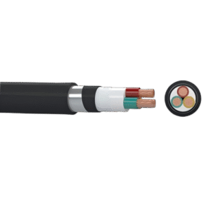
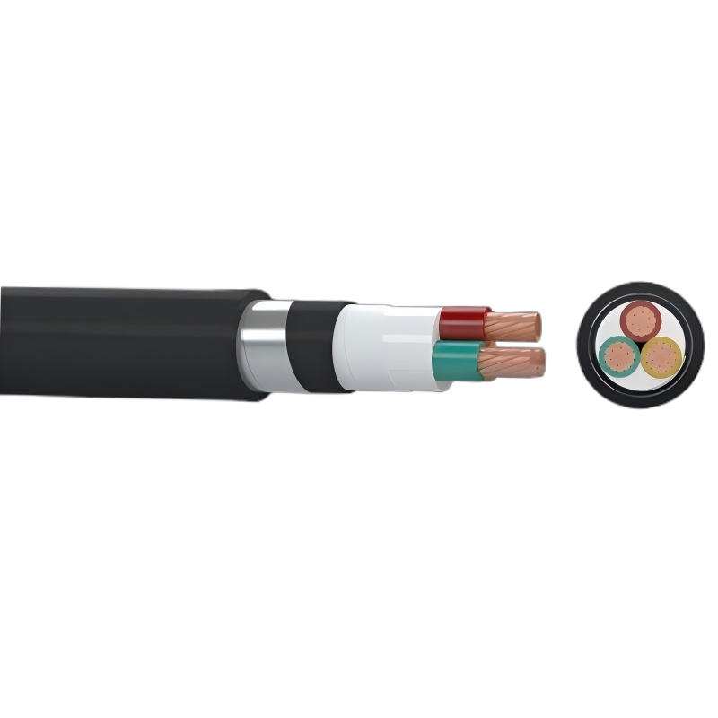
N2XBY – YJV62 YJV22 (Cu/XLPE/STA/PVC)
These power cables are used for electricity supply in low voltage installation systems. They are well adapted to underground use in industrial applications with an additional mechanical protection. These cables can be laying indoor, tunnel and underground. Able to bear external mechanical force, but unable to bear large pulling force.
Application
Our N2XBY – YJV22 cable is ideal for power supply in low-voltage systems. It performs reliably in industrial settings, especially for underground installations that require additional mechanical protection. You can install this versatile cable indoors, in tunnels, or directly buried underground. It is built to withstand external mechanical pressures, though it is not designed for installations with significant pulling tension.
Description
The N2XBY – YJV22 cable from Gongniu Cable features a robust, dual-layer protected construction for dependable performance.
- Conductor: It has a high-conductivity copper conductor, ensuring efficient electrical transmission.
- Insulation: The Cross-linked Polyethylene (XLPE) insulation provides superior electrical properties. This allows for a high power carrying capacity and ensures a long service life with minimal dielectric losses.
- Protection: For mechanical strength, the cable incorporates strong Steel Tape Armour (STA). This armour is complemented by an inner PVC bedding and a tough outer PVC sheath, forming a comprehensive protective system against external stresses, moisture, and chemical influences. This dual-layer protection enhances the cable’s durability.
- Outer Sheath: The outer PVC sheath offers good resistance to oils and abrasion, making the cable suitable for challenging industrial environments.
This careful construction ensures the cable delivers consistent power and safety.
Specification
- Conductor:
- Material: Annealed Copper (Cu)
- Type: Solid or stranded (Class 1 or 2), circular or circular compacted, conforming to IEC 60228
- Insulation:
- Material: Cross-linked Polyethylene (XLPE)
- Inner Sheath (Bedding):
- Material: Polyvinyl Chloride (PVC)
- Armour:
- Material: Steel Tape Armour (STA)
- Outer Sheath:
- Material: Polyvinyl Chloride (PVC)
- Color: Typically Black (custom colors available upon request)
- Rated Voltage (Uo/U (Um)):
- 0.6/1 kV (1.2 kV)
- Can also be supplied for 1.8/3 kV (3.6 kV) systems
- Maximum Conductor Operating Temperature: 90°C
- Key Characteristics:
- Excellent electrical and mechanical properties.
- High insulation resistance.
- Good protection against mechanical damage.
- Resistant to oil and abrasion.
- Applicable Standards:
- IEC 60502-1: Power cables with extruded insulation for rated voltages from 1 kV up to 30 kV.
- IEC 60228: Conductors of insulated cables.
Technical Parameter
| No. of Cores and Nominal Cross Section | Min. Number of Wires | Nominal Insulation Thickness | Nominal Steel Tape Thickness | Nominal Sheath Thickness | Approx. Overall Diameter | Approx. Weight | Max. D.C. Resistance of Conductor at 20℃ |
| No. × mm² | No. | mm | mm | mm | mm | kg/km | Ω/km |
| 2×1.5 | 1 | 0.7 | 0.2 | 1.8 | 12.2 | 220 | 12.1 |
| 2×2.5 | 1 | 0.7 | 0.2 | 1.8 | 13.0 | 256 | 7.41 |
| 2×4 | 1 | 0.7 | 0.2 | 1.8 | 14.0 | 307 | 4.61 |
| 2×6 | 1 | 0.7 | 0.2 | 1.8 | 15.0 | 370 | 3.08 |
| 2×10 | 6 | 0.7 | 0.2 | 1.8 | 17.5 | 509 | 1.83 |
| 2×16 | 6 | 0.7 | 0.2 | 1.8 | 19.1 | 659 | 1.15 |
| 2×25 | 6 | 0.9 | 0.2 | 1.8 | 22.3 | 915 | 0.727 |
| 2×35 | 6 | 0.9 | 0.2 | 1.8 | 24.3 | 1147 | 0.524 |
| 2×50 | 6 | 1.0 | 0.2 | 1.8 | 27.3 | 1463 | 0.387 |
| 2×70 | 12 | 1.1 | 0.2 | 1.9 | 30.9 | 1939 | 0.268 |
| 2×95 | 15 | 1.1 | 0.2 | 2.0 | 35.4 | 2587 | 0.193 |
| 2×120 | 18 | 1.2 | 0.5 | 2.2 | 40.2 | 3557 | 0.153 |
| 2×150 | 18 | 1.4 | 0.5 | 2.3 | 44.2 | 4269 | 0.124 |
| 2×185 | 30 | 1.6 | 0.5 | 2.5 | 49.0 | 5250 | 0.0991 |
| 2×240 | 34 | 1.7 | 0.5 | 2.6 | 54.2 | 6551 | 0.0754 |
| 2×300 | 34 | 1.8 | 0.5 | 2.8 | 59.8 | 8038 | 0.0601 |
| 2×400 | 53 | 2.0 | 0.5 | 3.0 | 66.6 | 10056 | 0.0470 |
| 3×1.5 | 1 | 0.7 | 0.2 | 1.8 | 12.7 | 246 | 12.1 |
| 3×2.5 | 1 | 0.7 | 0.2 | 1.8 | 13.5 | 292 | 7.41 |
| 3×4 | 1 | 0.7 | 0.2 | 1.8 | 14.5 | 359 | 4.61 |
| 3×6 | 1 | 0.7 | 0.2 | 1.8 | 15.6 | 441 | 3.08 |
| 3×10 | 6 | 0.7 | 0.2 | 1.8 | 18.4 | 621 | 1.83 |
| 3×16 | 6 | 0.7 | 0.2 | 1.8 | 20.1 | 827 | 1.15 |
| 3×25 | 6 | 0.9 | 0.2 | 1.8 | 23.5 | 1170 | 0.727 |
| 3X35 | 6 | 0.9 | 0.2 | 1.8 | 25.7 | 1491 | 0.524 |
| 3×50 | 6 | 1.0 | 0.2 | 1.8 | 28.9 | 1922 | 0.387 |
| 3×70 | 12 | 1.1 | 0.2 | 2.0 | 33.7 | 2657 | 0.268 |
| No. of Cores and Nominal Cross Section | Min. Number of Wires | Nominal Insulation Thickness | Nominal Steel Tape Thickness | Nominal Sheath Thickness | Approx. Overall Diameter | Approx. Weight | Max. D.C. Resistance of Conductor at 20℃ |
| No. × mm² | No. | mm | mm | mm | mm | kg/km | Ω/km |
| 3×95 | 15 | 1.1 | 0.5 | 2.2 | 39.2 | 3884 | 0.193 |
| 3×120 | 18 | 1.2 | 0.5 | 2.3 | 42.9 | 4728 | 0.153 |
| 3×150 | 18 | 1.4 | 0.5 | 2.4 | 47.6 | 5749 | 0.124 |
| 3×185 | 30 | 1.6 | 0.5 | 2.6 | 52.3 | 7045 | 0.0991 |
| 3×240 | 34 | 1.7 | 0.5 | 2.7 | 58.3 | 8927 | 0.0754 |
| 3×300 | 34 | 1.8 | 0.5 | 2.9 | 63.9 | 10919 | 0.0601 |
| 3×400 | 53 | 2.0 | 0.5 | 3.2 | 71.4 | 13772 | 0.0470 |
| 4×1.5 | 1 | 0.7 | 0.2 | 1.8 | 13.4 | 279 | 12.1 |
| 4×2.5 | 1 | 0.7 | 0.2 | 1.8 | 14.3 | 336 | 7.41 |
| 4×4 | 1 | 0.7 | 0.2 | 1.8 | 15.5 | 420 | 4.61 |
| 4×6 | 1 | 0.7 | 0.2 | 1.8 | 16.7 | 525 | 3.08 |
| 4×10 | 6 | 0.7 | 0.2 | 1.8 | 19.8 | 751 | 1.83 |
| 4×16 | 6 | 0.7 | 0.2 | 1.8 | 21.7 | 1016 | 1.15 |
| 4×25 | 6 | 0.9 | 0.2 | 1.8 | 25.6 | 1455 | 0.727 |
| 4×35 | 6 | 0.9 | 0.2 | 1.8 | 28.0 | 1871 | 0.524 |
| 4×50 | 6 | 1.0 | 0.2 | 1.9 | 31.8 | 2440 | 0.387 |
| 4×70 | 12 | 1.1 | 0.2 | 2.1 | 37.0 | 3387 | 0.268 |
| 4×95 | 15 | 1.1 | 0.5 | 2.3 | 43.0 | 4907 | 0.193 |
| 4×120 | 18 | 1.2 | 0.5 | 2.4 | 47.5 | 6044 | 0.153 |
| 4×150 | 18 | 1.4 | 0.5 | 2.6 | 52.5 | 7332 | 0.124 |
| 4×185 | 30 | 1.6 | 0.5 | 2.7 | 57.9 | 9048 | 0.0991 |
| 4×240 | 34 | 1.7 | 0.5 | 2.9 | 64.4 | 11449 | 0.0754 |
| 4×300 | 34 | 1.8 | 0.5 | 3.1 | 70.6 | 14041 | 0.0601 |
| 4×400 | 53 | 2.0 | 0.5 | 3.4 | 79.3 | 17835 | 0.0470 |
| 5×1.5 | 1 | 0.7 | 0.2 | 1.8 | 14.2 | 314 | 12.1 |
| 5×2.5 | 1 | 0.7 | 0.2 | 1.8 | 15.2 | 383 | 7.41 |
| 5×4 | 1 | 0.7 | 0.2 | 1.8 | 16.5 | 485 | 4.61 |
| 5×6 | 1 | 0.7 | 0.2 | 1.8 | 17.9 | 613 | 3.08 |
| 5×10 | 6 | 0.7 | 0.2 | 1.8 | 21.3 | 886 | 1.83 |
| 5×16 | 6 | 0.7 | 0.2 | 1.8 | 23.4 | 1212 | 1.15 |
| No. of Cores and Nominal Cross Section | Min. Number of Wires | Nominal Insulation Thickness | Nominal Steel Tape Thickness | Nominal Sheath Thickness | Approx. Overall Diameter | Approx. Weight | Max. D.C. Resistance of Conductor at 20℃ |
| No.× mm² | No. | mm | mm | mm | mm | kg/km | Ω/km |
| 5×25 | 6 | 0.9 | 0.2 | 1.8 | 27.8 | 1751 | 0.727 |
| 5×35 | 6 | 0.9 | 0.2 | 1.9 | 30.7 | 2277 | 0.524 |
| 5×50 | 6 | 1.0 | 0.2 | 2.0 | 35.6 | 3029 | 0.387 |
| 5×70 | 12 | 1.1 | 0.5 | 2.3 | 42.0 | 4551 | 0.268 |
| 5×95 | 15 | 1.1 | 0.5 | 2.4 | 47.5 | 6006 | 0.193 |
| 5×120 | 18 | 1.2 | 0.5 | 2.5 | 52.0 | 7354 | 0.153 |
| 5×150 | 18 | 1.4 | 0.5 | 2.7 | 57.9 | 8999 | 0.124 |
| 5×185 | 30 | 1.6 | 0.5 | 2.9 | 63.7 | 11074 | 0.0991 |
| 5×240 | 34 | 1.7 | 0.5 | 3.1 | 70.9 | 14042 | 0.0754 |
| 5×300 | 34 | 1.8 | 0.5 | 3.4 | 78.3 | 17364 | 0.0601 |
| 5×400 | 53 | 2.0 | 0.8 | 3.7 | 88.8 | 22823 | 0.0470 |
| 3×2.5+1×1.5 | 1/1 | 0.7/0.7 | 0.2 | 1.8 | 14.1 | 322 | 7.41/12.1 |
| 3×4+1×2.5 | 1/1 | 0.7/0.7 | 0.2 | 1.8 | 15.2 | 399 | 4.61/7.41 |
| 3×6+1×4 | 1/1 | 0.7/0.7 | 0.2 | 1.8 | 16.4 | 499 | 3.08/4.61 |
| 3×10+1×6 | 6/1 | 0.7/0.7 | 0.2 | 1.8 | 19.0 | 694 | 1.83/3.08 |
| 3×16+1×10 | 6/6 | 0.7/0.7 | 0.2 | 1.8 | 21.2 | 949 | 1.15/1.83 |
| 3×25+1×16 | 6/6 | 0.9/0.7 | 0.2 | 1.8 | 24.6 | 1344 | 0.727/1.15 |
| 3×35+1×16 | 6/6 | 0.9/0.7 | 0.2 | 1.8 | 26.4 | 1653 | 0.524/1.15 |
| 3×50+1×25 | 6/6 | 1.0/0.9 | 0.2 | 1.9 | 30.3 | 2194 | 0.387/0.727 |
| 3×70+1×35 | 12/6 | 1.1/0.9 | 0.2 | 2.0 | 34.9 | 3005 | 0.268/0.524 |
| 3×95+1×50 | 15/6 | 1.1/1.0 | 0.5 | 2.2 | 40.7 | 4369 | 0.193/0.387 |
| 3×120+1×70 | 18/12 | 1.2/1.1 | 0.5 | 2.3 | 44.8 | 5424 | 0.153/0.268 |
| 3×150+1×70 | 18/12 | 1.4/1.1 | 0.5 | 2.5 | 49.1 | 6433 | 0.124/0.268 |
| 3×185+1×95 | 30/15 | 1.6/1.1 | 0.5 | 2.6 | 54.0 | 7959 | 0.0991/0.193 |
| 3×240+1×120 | 34/18 | 1.7/1.2 | 0.5 | 2.8 | 60.3 | 10095 | 0.0754/0.153 |
| 3×300+1×150 | 34/18 | 1.8/1.4 | 0.5 | 3.0 | 66.2 | 12359 | 0.0601/0.124 |
| 3×400+1×185 | 53/30 | 2.0/1.6 | 0.5 | 3.2 | 74.0 | 15608 | 0.0470/0.0991 |
| 3×2.5+2×1.5 | 1/1 | 0.7/0.7 | 0.2 | 1.8 | 14.8 | 355 | 7.41/12.1 |
| 3×4+2×2.5 | 1/1 | 0.7/0.7 | 0.2 | 1.8 | 16.0 | 444 | 4.61/7.41 |
| 3×6+2×4 | 1/1 | 0.7/0.7 | 0.2 | 1.8 | 17.3 | 562 | 3.08/4.61 |
| No. of Cores and Nominal Cross Section | Min. Number of Wires | Nominal Insulation Thickness | Nominal Steel Tape Thickness | Nominal Sheath Thickness | Approx. Overall Diameter | Approx. Weight | Max. D.C. Resistance of Conductor at 20℃ |
| No.× mm² | No. | mm | mm | mm | mm | kg/km | Ω/km |
| 3×10+2×6 | 6/1 | 0.7/0.7 | 0.2 | 1.8 | 19.9 | 776 | 1.83/3.08 |
| 3×16+2×10 | 6/6 | 0.7/0.7 | 0.2 | 1.8 | 22.6 | 1081 | 1.15/1.83 |
| 3×25+2×16 | 6/6 | 0.9/0.7 | 0.2 | 1.8 | 26.0 | 1532 | 0.727/1.15 |
| 3×35+2×16 | 6/6 | 0.9/0.7 | 0.2 | 1.8 | 27.7 | 1836 | 0.524/1.15 |
| 3×50+2×25 | 6/6 | 1.0/0.9 | 0.2 | 1.9 | 32.7 | 2525 | 0.387/0.727 |
| 3×70+2×35 | 12/6 | 1.1/0.9 | 0.2 | 2.1 | 36.9 | 3399 | 0.268/0.524 |
| 3×95+2×50 | 15/6 | 1.1/1.0 | 0.5 | 2.3 | 43.1 | 4917 | 0.193/0.387 |
| 3×120+2×70 | 18/12 | 1.2/1.1 | 0.5 | 2.4 | 48.1 | 6235 | 0.153/0.268 |
| 3×150+2×70 | 18/12 | 1.4/1.1 | 0.5 | 2.5 | 51.4 | 7165 | 0.124/0.268 |
| 3×185+2×95 | 30/15 | 1.6/1.1 | 0.5 | 2.7 | 57.4 | 9040 | 0.0991/0.193 |
| 3×240+2×120 | 34/18 | 1.7/1.2 | 0.5 | 2.9 | 63.5 | 11363 | 0.0754/0.153 |
| 3×300+2×150 | 34/18 | 1.8/1.4 | 0.5 | 3.1 | 69.9 | 13917 | 0.0601/0.124 |
| 3×400+2×185 | 53/30 | 2.0/1.6 | 0.5 | 3.4 | 78.2 | 17581 | 0.0470/0.0991 |
| 4×2.5+1×1.5 | 1/1 | 0.7/0.7 | 0.2 | 1.8 | 15.0 | 369 | 7.41/12.1 |
| 4×4+1×2.5 | 1/1 | 0.7/0.7 | 0.2 | 1.8 | 16.2 | 464 | 4.61/7.41 |
| 4×6+1×4 | 1/1 | 0.7/0.7 | 0.2 | 1.8 | 17.6 | 587 | 3.08/4.61 |
| 4×10+1×6 | 6/1 | 0.7/0.7 | 0.2 | 1.8 | 20.6 | 831 | 1.83/3.08 |
| 4×16+1×10 | 6/6 | 0.7/0.7 | 0.2 | 1.8 | 23.0 | 1147 | 1.15/1.83 |
| 4×25+1×16 | 6/6 | 0.9/0.7 | 0.2 | 1.8 | 26.9 | 1641 | 0.727/1.15 |
| 4×35+1×16 | 6/6 | 0.9/0.7 | 0.2 | 1.8 | 29.1 | 2049 | 0.524/1.15 |
| 4×50+1×25 | 6/6 | 1.0/0.9 | 0.2 | 2.0 | 34.3 | 2783 | 0.387/0.727 |
| 4×70+1×35 | 12/6 | 1.1/0.9 | 0.5 | 2.2 | 40.1 | 4152 | 0.268/0.524 |
| 4×95+1×50 | 15/6 | 1.1/1.0 | 0.5 | 2.3 | 45.0 | 5427 | 0.193/0.387 |
| 4×120+1×70 | 18/12 | 1.2/1.1 | 0.5 | 2.5 | 50.1 | 6804 | 0.153/0.268 |
| 4×150+1×70 | 18/12 | 1.4/1.1 | 0.5 | 2.6 | 54.4 | 8047 | 0.124/0.268 |
| 4×185+1×95 | 30/15 | 1.6/1.1 | 0.5 | 2.8 | 60.5 | 10052 | 0.0991/0.193 |
| 4×240+1×120 | 34/18 | 1.7/1.2 | 0.5 | 3.0 | 67.2 | 12697 | 0.0754/0.153 |
| 4×300+1×150 | 34/18 | 1.8/1.4 | 0.5 | 3.2 | 74.2 | 15654 | 0.0601/0.124 |
| 4×400+1×185 | 53/30 | 2.0/1.6 | 0.8 | 3.6 | 84.2 | 20594 | 0.0470/0.0991 |
YOU MAY LIKE
Related products
-
Copper Conductor Products
NYY – VV (Cu/PVC/PVC)
-
Copper Conductor Products
NYRY – VV32 (Cu/PVC/SWA/PVC)
-
Copper Conductor Products
NYBY – VV62 VV22(Cu/PVC/PVC/DSTA/PVC)
-
Copper Conductor Products
N2XY – YJV (Cu/XLPE/PVC)
-
Copper Conductor Products
N2XRY – YJV72 YJV32 (Cu/XLPE/SWA/PVC)